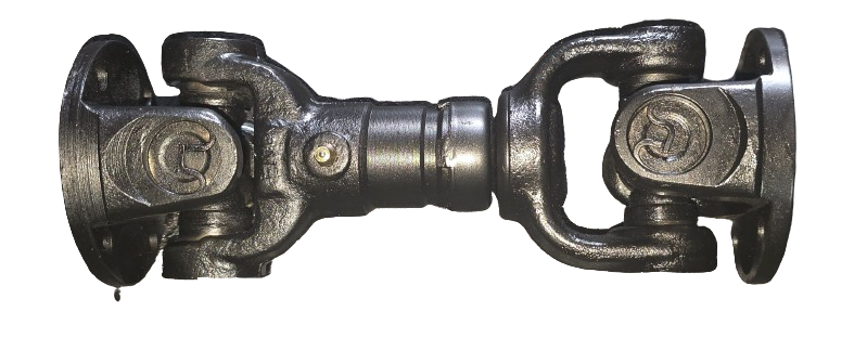
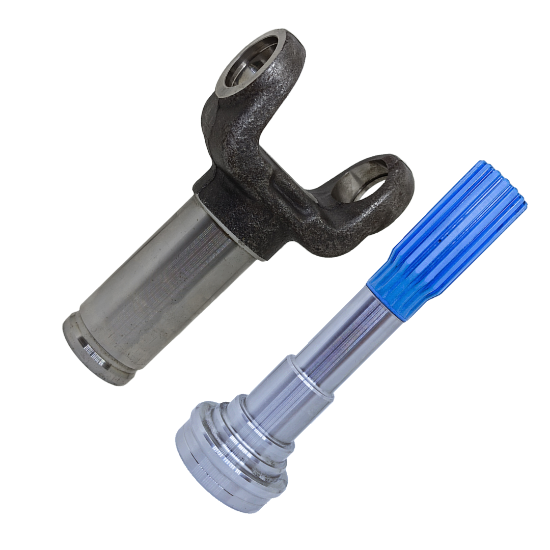
A flange yoke connects a propeller shaft to a differential pinion or gearbox output through a set of bolts arranged in a circle. It looks like one of the simplest interfaces on the whole driveline, which is exactly why mismatches slip through — a flange can look correct from across the workshop and still be the wrong part once it's held up against the mating flange.
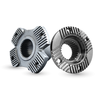
The Three Things That Actually Have To Match
Bolt circle diameter (PCD). This is the diameter of the imaginary circle passing through the center of every bolt hole, not the outside diameter of the flange itself. Two flanges can have the same overall diameter and a different PCD, or vice versa — the outside edge of the flange tells you almost nothing about whether the bolts will line up.
Number of bolt holes. Four, six, and eight-hole patterns are all common across different vehicle platforms and torque ratings, and a higher bolt count generally signals a higher-torque application. A flange with the right PCD but the wrong hole count simply won't have anywhere to put every bolt.
Pilot boss diameter. Many flange couplings use a raised or recessed pilot — a boss — that centers the two flanges relative to each other before the bolts are tightened, taking shear load off the bolts themselves and keeping the joint concentric. A mismatched pilot boss can let two flanges bolt together while sitting slightly off-center, which introduces exactly the kind of misalignment covered in our guide on driveline angles and phasing — except at the flange itself rather than at a universal joint.
Why This Causes More Wasted Orders Than Almost Anything Else
Someone describing a flange over the phone will almost always describe the overall shape and diameter, because that's what's visually obvious. PCD and pilot boss diameter require actually measuring with calipers, and they're easy to skip when the part "looks standard." The fix is simple: measure center-to-center across two bolt holes on opposite sides of the circle for a rough PCD figure, count the holes, and measure the pilot boss (or bore, if it's a recessed pilot) directly. Send all three along with the working length covered in our measurement guide, and fitment stops being a guess.
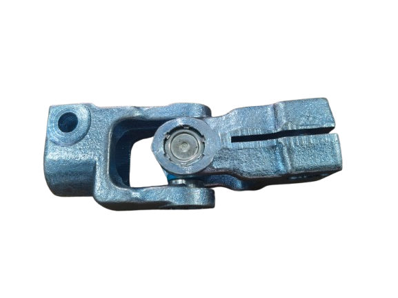
Photographs Solve This Faster Than Descriptions
A straight-on photo of the flange face, taken square to the bolt pattern rather than at an angle, lets an experienced fabricator estimate the PCD and hole count directly from the image in many cases, and it catches details — like whether the holes are threaded or clearance, or whether there's a raised pilot at all — that a verbal description usually misses entirely.
Matching A Flange Coupling?
Send us a straight-on photo of the flange face plus the pilot boss measurement, and we'll confirm the pattern before you order.
Torque Matters As Much As Fit
Even a correctly matched flange coupling depends on correct bolt torque and, on some applications, the right grade of bolt. Under-torqued flange bolts loosen under cyclic load and produce exactly the kind of clunk covered in our guide on diagnosing drive shaft vibration — always worth checking before assuming the flange itself has failed.