Most wrong propeller shafts are not wrong because the manufacturer made a mistake. They are wrong because the order said "Tata 2518 rear shaft, 1300mm" and nothing else — no joint series, no flange bolt circle, no note on which end was which. A shaft built to that description will arrive, and it will not fit.
The good news is that the measurements a driveline shop actually needs are not difficult. A steel tape, a vernier caliper and twenty minutes under the vehicle will get you all of them. This guide walks through each one in the order we would take them ourselves, and ends with the exact checklist to send us on WhatsApp.

Before You Pick Up The Tape
Drop the shaft out of the vehicle if you can. Measuring a shaft in situ, lying on your back with the tape hooked over a crossmember, is how 15mm errors happen. Once it is on the bench, wipe the tube down — paint flakes and dried mud will cost you a millimetre on every caliper reading and hide the part numbers stamped into the yokes.
And before anything else: mark the shaft. Put a paint or punch mark on the tube at the transmission end, and a second mark showing the phasing of the two yokes relative to each other. Phasing matters — on a single-piece shaft the two end yokes should be in the same plane, so that the speed fluctuation the front joint creates is cancelled by the rear joint. If you are replacing a shaft that ran smoothly, you want the new one phased the same way.
If the old shaft is bent, twisted or the tube is dented, note that too. A damaged shaft can still be measured, but tube damage usually means something else in the driveline took a hit as well.
Step 1: Length — Centre To Centre, Compressed And Extended
This is the measurement everything else hangs off, and it is the one most often taken wrongly.
The standard reference is centre of the front U-joint to centre of the rear U-joint. Not flange face to flange face. Not the overall length including the yoke ears. Centre of cross to centre of cross — the two points the shaft actually pivots about. Find the centre by measuring across the outside of the two opposing bearing caps and halving it, or simply lay your tape from the centreline of one cross to the centreline of the other with the shaft flat on the bench.
If the shaft has a slip section — a splined sleeve yoke — you need two lengths, not one:
- Compressed (collapsed) length: push the slip yoke fully home against its internal stop, then measure centre to centre.
- Extended length: pull the slip yoke out until it is just about to disengage the spline, then measure again.
The difference between the two is your available slip travel. On a working shaft the yoke should sit roughly in the middle of that travel at ride height — never bottomed out, never near the end of engagement. A slip yoke that bottoms out on a bad haul road will push hard against the gearbox tail housing or the differential nose, and that load has to go somewhere. It usually goes into a bearing.
For a two-piece or three-piece shaft, measure each section separately and tell us where the centre bearing mounts. The centre bearing and coupling flange position is a dimension in its own right: from the front joint centre to the centre of the bearing hanger.
Step 2: Tube Outside Diameter And Wall Thickness
Wrap a tape around the tube and divide by π, or use a caliper across the tube if you have one wide enough. Measure on a clean, undented section away from the weld yokes. Common heavy commercial sizes sit in the 75mm to 120mm range, but measure — do not assume from the vehicle model, because the same chassis is often built with different tube sizes depending on the rear axle ratio and duty rating.
Wall thickness is harder without an ultrasonic gauge, but if the old shaft has a cut end, a damaged section, or you are willing to check at the weld yoke, a caliper will give you a usable figure. If you genuinely cannot measure it, say so and tell us the application and GVW instead. Tube OD and wall together set the torsional capacity and, just as importantly, the critical speed of the shaft — the rpm at which a straight tube starts to whip. Longer shafts need larger diameter tube for exactly this reason, which is why a long-wheelbase truck gets a two-piece shaft rather than one very long single piece.
Step 3: Identify The Joint Series
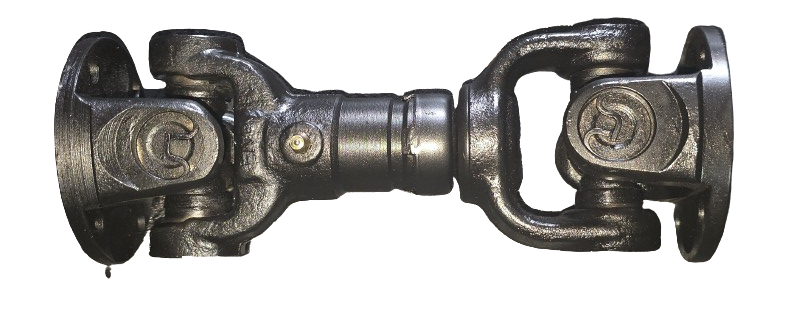
The universal joint series is defined by two numbers: the bearing cap outside diameter and the overall span across the caps (cap face to cap face, across the fitted cross). Measure the cap OD with a caliper on a cap that has not been hammered out of shape, and measure the span across two opposite caps while the cross is still assembled.
Then note the retention style, because two joints with identical cap dimensions can be completely different parts:
- Inside snap ring — circlip sits in a groove inside the yoke ear, behind the cap.
- Outside snap ring — circlip sits in a groove on the cap itself, outboard of the yoke.
- Bearing plate / strap retained — caps held by a pressed plate or U-strap with two bolts. Note the bolt spacing and thread size.
Also count the grease provision. Is there a zerk in the centre of the cross, is it a sealed-for-life joint, and is the nipple in the body of the cross or in one of the yoke ears? It tells us which cross and bearing kit you are on.
Step 4: Identify The Flanges
Each end of the shaft mates to something — a gearbox output flange, a differential pinion flange, a centre bearing coupling. For every flange, record three things.
Bolt-hole count and bolt circle diameter
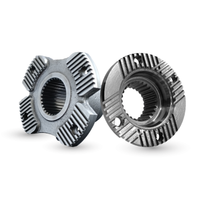
Count the holes: four, six and eight are all common. Then measure the bolt circle diameter (PCD) — the diameter of the imaginary circle through the centres of the bolt holes. On an even hole count this is easy: measure centre to centre across two directly opposite holes. On an odd count, measure from the centre of one hole to the far edge of the hole opposite it. Note the hole diameter and, if the flange is bolted up, the bolt thread size across flats.
Flange OD and pilot
Measure the outside diameter of the flange face, and check whether there is a raised or recessed pilot boss in the centre that locates into the mating flange. If there is, measure its diameter and depth. A shaft with the wrong pilot will not sit square no matter how well the bolt holes line up.
Face type
Is it a plain flat flange, a half-round flange, or a face-splined (serrated) flange with radial teeth? Serrated flanges are common on heavier drivelines and the serration count and pitch must match exactly — photograph it clearly.
Step 5: Splines — Count And Measure
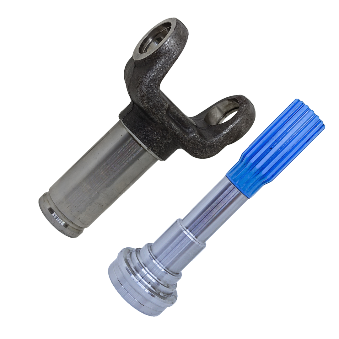
If either end is a slip yoke or a stub shaft rather than a flange, the spline is the critical dimension. Take three readings:
- Number of teeth. Count them. Mark your starting tooth with a marker so you do not lose your place; a 16-tooth and an 18-tooth spline of the same diameter look very similar at arm's length.
- Major (outside) diameter — caliper across the tips of the teeth on a male spline, or across the roots on a female bore.
- Spline length and overall stub length — from the shoulder to the end of the splined section, plus the full length of the stub from flange face or joint centre.
Note whether the spline is straight-sided or involute, whether there is a blocked (missing) tooth used for phasing, and whether the end is threaded for a retaining nut. On a PTO or machinery shaft also note any shear pin or quick-release collar arrangement.
Send Us Your Measurements
Photos and six numbers are usually enough for us to quote and build. If anything is unclear, our engineers will tell you exactly what else to check before you order.
The Checklist — Exactly What To Send Us
Copy this, fill it in, and send it with the photos. If every line is answered, we can quote from it directly and build to it.
| What to send | Enough to build from | Not enough |
|---|---|---|
| Length | Compressed AND extended, joint centre to joint centre, in mm | "About 1300mm" |
| Tube | Outside diameter and wall thickness | Vehicle model only |
| Joint | Cap OD, span across caps, snap-ring or plate style | "Standard UJ" |
| Flanges | Hole count, PCD, flange OD, pilot, flat or serrated | "Four bolt flange" |
| Splines | Tooth count, major diameter, spline length | Photo of the yoke from a distance |
| Orientation | Which end is gearbox, which is axle, yoke phasing | Nothing stated |
Add to that: vehicle make, model and GVW; the application (tipper, bus, tractor-trailer, industrial or earthmoving machine); whether it is a single, two-piece or three-piece shaft; and whether the old shaft failed or is simply worn. Failure mode tells us a lot. A shaft that sheared at the weld is a different conversation from one that wore out its splines.
Photographs That Actually Help
Six shots, in daylight, with the shaft clean: the full shaft laid out straight; both ends square-on to the flange or yoke face; the slip section with the yoke pushed in; a close-up of any stamped part number; and one with a steel rule laid across the flange so we can sanity-check your PCD.
What Happens After You Send It
Once we have the sheet, the build is straightforward. Tube is cut and the yokes are welded to your centre-to-centre dimension, the slip spline is CNC-broached, and the finished shaft goes onto the dynamic balancer — every shaft, not a sample. Dynamic balancing is what keeps a correctly-sized shaft from behaving like a wrongly-sized one at 90 km/h. You can see the machining and balancing setup on our infrastructure page.
If your part is a standard fitment we hold in stock — equivalents for Tata, Ashok Leyland, Eicher, BharatBenz, Mahindra, Volvo and JCB drivelines among others — ready stock dispatches within 72 hours. If it is a custom build, the measurements above are what set the schedule.
Not sure about one of the readings? Send what you have anyway. It is far quicker for us to ask you to re-check one number than for you to receive a shaft that is 20mm too long. Get in touch and we will work through it with you.