A shaft comes back to us with the bearing cups blued at the base of the trunnions and the needles flattened on one side. The customer says it started humming at 60 km/h about a month after a rebuild, then got worse. The shaft itself is fine. The joints are fine — or they were. What killed them was the geometry they were asked to run in.
This is the most common failure we see that has nothing to do with the part. A propeller shaft is not a rigid stick that just spins. It is a machine with its own internal behaviour, and if you install it in the wrong geometry it will tear itself apart no matter whose name is stamped on the tube.
Why a U-Joint at an Angle Does Not Turn Evenly
A Cardan (Hooke's) universal joint transmits torque through a cross whose two axes stay perpendicular to each other. When the input and output shafts are in a straight line, the cross rotates in a single plane and the output turns at exactly the same speed as the input. Put the two shafts at an angle and that stops being true.
At an angle, the cross has to swing through an arc as it rotates. Over one revolution of the input, the output runs ahead of it, falls back to level, runs behind, and levels again — two full speed fluctuations for every single turn. The input is dead steady at, say, 2,500 rpm. The output is oscillating above and below 2,500 rpm, twice per revolution, forever.
Two things follow from that, and both matter more than most workshops realise:
- The variation grows fast with angle. It is not linear. Doubling the working angle more than doubles the speed fluctuation. A joint at one degree is barely doing anything. The same joint at eight degrees is a vibration source.
- It scales with speed. The percentage variation depends only on angle, but the actual acceleration the parts feel — the force — rises with the square of shaft rpm. This is why a shaft that behaves perfectly around the yard starts shaking on a highway run.
That twice-per-revolution pulse is what engineers call second-order vibration. You feel it as a hum or a buzz through the floor that comes in at a particular speed band, gets worse as you go faster, and often disappears again at the top end. It loads the transmission output bearing, the differential pinion bearing and the centre bearing with a pulsing side force they were never meant to carry continuously.
How Two Joints Cancel Each Other Out
The whole trick of a conventional propeller shaft is that the first joint's speed error is corrected by the second one. If the rear joint accelerates exactly when the front joint decelerates, the two cancel and the differential sees smooth rotation.
For that cancellation to happen, three conditions have to hold at the same time:
- Equal working angles. The angle at the gearbox end and the angle at the axle end must be the same, within a fraction of a degree. Not "close". The same.
- Opposite direction. The two angles must bend the driveline in opposite senses, so the errors subtract rather than add.
- Correct phasing. The two yokes on the intermediate shaft must be in the same plane as each other.
Break any one of those and the cancellation is incomplete. Break phasing and it is not just incomplete — it is inverted, and the two joints add their errors together instead of subtracting them.
Working Angle vs Operating Angle
These two terms get used interchangeably on the shop floor, and they should not be.
The operating angle is the true angle of articulation at a single joint — the angle between the shaft going in and the shaft coming out, measured at that joint, in three dimensions.
The working angle is what you are actually managing when you set up a driveline: the relationship between the angles at each end of the same shaft. Two joints can each have a healthy operating angle and still be badly matched to one another. A driveline is only as good as the difference between its two working angles, not the size of either one.
In practice you measure the inclination of three things with a digital angle finder or an inclinometer: the transmission output, the propeller shaft tube, and the pinion nose. The difference between output and tube is the front joint's angle. The difference between tube and pinion is the rear joint's angle. You want those two numbers to match, and you want the sign convention to be opposite.
Why Zero Degrees Is Worse Than Three
Here is the part that surprises people: a perfectly straight driveline with zero angle at both joints is a failure waiting to happen.
A universal joint's needle rollers only roll because the joint articulates. That small back-and-forth swing each revolution is what makes the needles turn in their cups and what drags fresh grease across the trunnion surface. Take the articulation away and the needles stop rolling. They just sit there taking load in one spot while the shaft spins.
What follows is false brinelling — the needles hammer flat-bottomed depressions into the trunnion and the cup race, the grease film is squeezed out and never replenished, and the joint develops a notchy feel and then a knock. The joint fails from lack of work, not from too much of it. We have opened up crosses off near-straight drivelines with polished, dished trunnions and perfect hardness, killed by geometry alone. It is a waste of a good induction-hardened cross.
So the target is not zero. The target is a small, deliberate, equal-and-opposite angle at both joints: enough to keep the needles rolling and the grease moving, small enough that the second-order pulse stays negligible. Manufacturers publish specific limits per application, and those limits tighten as shaft speed rises — a high-rpm shaft tolerates far less angle than a slow one. As a working principle: a couple of degrees is healthy, matched is essential, and large angles at high rpm are what break things.
Not Sure Your Driveline Geometry Is Right?
Send us your vehicle model, shaft length, ride height changes and joint angles. Our engineering team will tell you whether the layout is workable and what shaft configuration suits it — before you buy anything.
Phasing: The Mistake That Happens During Reassembly
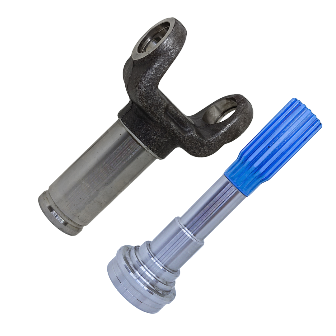
Phasing is simple to state and easy to get wrong. On a shaft with a slip joint — a splined sleeve yoke sliding on a splined stub — the yoke at each end of that shaft must have its ears lying in the same plane. Looking down the length of the shaft, the two yokes should line up with each other, not be rotated apart.
That alignment is what makes the second joint's speed error the exact mirror of the first one's. Rotate one yoke relative to the other and the two joints stop cancelling. In the worst case — a quarter turn out — the two errors reinforce instead of subtract, and the driveline delivers roughly double the speed fluctuation of a single joint. The vehicle shudders, the noise is immediate and obvious, and the joints, the centre bearing and the pinion start wearing at a rate you can measure in weeks.
It happens because a slip yoke pulls apart easily during a clutch or gearbox job, and goes back together in whatever orientation gravity offers. The splines do not care. The driveline does.
How to Check Phasing Visually
You do not need a tool for this. On a two-piece or slip-jointed shaft:
- Before you separate anything, punch or paint a match mark across the slip joint — one line spanning the sleeve and the stub. Reassembling to that line is the whole job.
- If it is already apart, sight down the shaft from one end. The yoke ears at the near end and the yoke ears at the far end should appear parallel — both horizontal, or both vertical, together.
- Lay the shaft on a flat bench. Both yoke openings should face the same way. If one opens upward and the other opens sideways, it is out of phase.
- On many production shafts there is a master spline — one tooth wider or a blind spline — that allows assembly in only one orientation. If yours has one, it has already made the decision for you. If it does not, the responsibility is yours.
One caution: on a two-piece shaft with a centre bearing, the phasing rule applies to the yokes on each individual shaft section, and the front section's geometry is set by the centre bearing's height. Shimming the centre bearing to correct a vibration changes working angles on both sections at once. Move it in small increments and re-measure.
Lift Kits, Re-Leafing and Changed Ride Height
Nothing wrecks driveline geometry faster than changing ride height without thinking about it. This applies to a lifted 4x4, but far more often in commercial fleets it applies to something more mundane: re-leafing a tipper's rear springs, fitting heavier-rated packs, replacing sagged suspension on an old bus, or lengthening a wheelbase for a new body.
Raising the body relative to the axle does two things. It increases the angle at both joints, and it usually increases them unequally, because the transmission and the axle are not raised by the same amount. A driveline that was matched at two degrees each end can end up at four degrees at the front and seven at the rear. Now nothing cancels, and the residual pulse runs straight into the pinion bearings.
It also shortens the effective distance in a way the slip joint has to absorb, and on a long shaft it can push the assembly closer to its critical speed — the rpm at which the tube's own natural bending frequency is excited and the shaft begins to whip. Longer shafts have lower critical speeds. This is why a wheelbase extension often needs a two-piece shaft with a centre bearing rather than one long tube.
The fix after a ride height change is not a new shaft. It is correcting the geometry: shimming or wedging the axle to rotate the pinion nose back into line with the transmission output, or repositioning the centre bearing. Fit a new shaft into bad geometry and you will be buying another one.
| Symptom | Likely Geometry Cause |
|---|---|
| Hum or buzz rising with road speed | Unequal working angles — second-order vibration not cancelling |
| Heavy shudder immediately after a gearbox job | Slip yoke reassembled out of phase |
| Knock on take-up, notchy joints, low mileage | Near-zero operating angle — false brinelling of the needles |
| Vibration only above a narrow speed band | Shaft approaching critical speed — length or support issue |
| Repeat centre bearing failures | Centre bearing height wrong; both shaft sections mis-angled |
What This Means When You Buy a Shaft
Geometry is the installer's job. What the manufacturer owes you is a shaft that does not add problems of its own on top of it — one where the yokes are machined true to the tube, the splines are cut to size so the slip joint does not bind or rattle, the tube runs straight, and the assembly is dynamically balanced so there is no first-order imbalance stacked on top of your second-order angle pulse.
That is why every shaft leaving our DSIDC Bawana units is 100% dynamically balanced, not batch-sampled, and why we hold UJ cross tolerances to within 0.01mm on European CNC equipment with SPC measurement at critical stages. When a customer calls about a vibration, we want to be able to rule the part out in the first minute and get straight to the geometry.
If you are specifying a shaft for a modified vehicle, a re-bodied chassis or an extended wheelbase, tell us the layout before you order. Length, joint series, flange pattern and whether it needs to be one piece or two are all decided by the geometry it has to live in. You can browse the full range on our products page, but on anything non-standard a five-minute conversation saves a return.